Saturday, March 28, 2015

Graphics Blitting in Unity Part 2: Caustics

I know I promised to do something with ping pong buffers but I remembered an effect I did a few months ago to simulate caustics using a light cookie.  You might have seen some tutorials or assets on the store that do something like this.  Usually these techniques involve having a bunch of pre-baked images and cycling through them, changing the image each frame.  The issues with this technique are that the animation rate of your caustics is going to fluctuate with the frame rate of your game, and of course that you need a bunch of images taking up memory.  You also need a program to generate your pre-baked images.

If this were unreal you could set up a material as a light function and project your caustics shader with the light.  This isn't a bad way to go but you end up computing the shader for every pixel the light touches times however many lights you have projecting it.  Your source textures might be really low (512x512) but you may be running a shader on the entire screen and then some.

This leads me to a solution that I think is pretty good.  Pre-compute one frame of a caustics animation using a shader and project that image with however many lights you want.


Web Player

Asset Package

In the package there is a shader, material, and render texture, along with 3 images that the material uses to generate the caustics.  There is a script that you put on a light (or anything in your scene) that stores a specified render texture, material, and image.  In the same script file there is a static class that is what actually does the work.  The script sends the information it's holding to the static class and the static class remembers what render textures it has blitted to.  If it is told to blit to a render texture that has already been blitted to that frame it will skip over it.  This is good for if you goof and copy a light that has script on it a bunch of times, the static class will keep the duplicate scripts from blitting over each other's render textures.  Now you can use the render texture as a light cookie!  The cookie changes every frame and only gets calculated once per frame instead of once per light.

Some optimizations would be to remove caustic generators when you are not able to see them, or have a caustics manager in the scene instead of a static class attached to the generator script.  The command buffer post on Unity's blog has a package that shows how to use sort of a manager for stuff like this so check it out!

Thursday, March 19, 2015

Graphics Blitting in Unity Part 1

Gas Giant Planet Shader Using Ping Pong Buffers

A very powerful feature in Unity is the ability to blit or render a new texture from an existing set of texture using a custom shader.  This is how many post process effects are done such as bloom, screen space ambient occlusion, and god rays.  There are many more uses for blitting than just post process effects and I'm going to go over a few of them in the next few posts starting with uses for standard separable blur and moving on to ping pong buffers to create cool effects like the gas giant planet shown above.

First example is a separable blur shader and how to use it to put a glow around a character icon.  This idea came from some one in the Unity3D sub-reddit who was looking for a way of automating glows around their character icons.  Get the package here!


So separable blur, separable means that the blurring is separated into 2 passes, horizontal and vertical.  It's 2 passes but we can use the same shader for both passes by telling it what direction to blur the image in.

First lets have a look at the shader.

Shader "Hidden/SeperableBlur" {
Properties {
_MainTex ("Base (RGB)", 2D) = "black" {}
}

CGINCLUDE

#include "UnityCG.cginc"
#pragma glsl

Starts out pretty simple, only one exposed property, but wait, whats that CGINCLUDE?  And no Subshader or Pass?  CGINCLUDE is used instead of CGPROGRAM when you want to have a shader that can do lots of things.  You make the include section first and then put your subshader section below with multiple passes that reference the vertex and fragment programs you write in the the include section.

struct v2f {
float4 pos : POSITION;
float2 uv : TEXCOORD0;
};

We don't need to pass much information the the fragment shader.  Position and uv is all we need.

//Common Vertex Shader
v2f vert( appdata_img v )
{
v2f o;
o.pos = mul (UNITY_MATRIX_MVP, v.vertex);
o.uv = v.texcoord.xy;
return o;
}

appdata_img is defined in UnityCG.cginc as being the standard information that you need for blitting stuff.  The rest is straight forward, just pass the uv to the fragment.

half4 frag(v2f IN) : COLOR
{
half2 ScreenUV = IN.uv;

float2 blurDir = _BlurDir.xy;
float2 pixelSize = float2( 1.0 / _SizeX, 1.0 / _SizeY );

I know it says half4 but the textures we are using only store 1 channel.  Save the UV's to a variable for convenience.  Same with the blurDir (blur direction), I'll talk about this more later but this variable is passed in from script.  And pixelSize is the normalized size of a pixel in uv space.  The size of the image is passed to the shader from script as well.

float4 Scene = tex2D( _MainTex, ScreenUV ) * 0.1438749;

Scene += tex2D( _MainTex, ScreenUV + ( blurDir * pixelSize * _BlurSpread ) ) * 0.1367508;
Scene += tex2D( _MainTex, ScreenUV + ( blurDir * pixelSize * 2.0 * _BlurSpread ) ) * 0.1167897;
Scene += tex2D( _MainTex, ScreenUV + ( blurDir * pixelSize * 3.0 * _BlurSpread ) ) * 0.08794503;
Scene += tex2D( _MainTex, ScreenUV + ( blurDir * pixelSize * 4.0 * _BlurSpread ) ) * 0.05592986;
Scene += tex2D( _MainTex, ScreenUV + ( blurDir * pixelSize * 5.0 * _BlurSpread ) ) * 0.02708518;
Scene += tex2D( _MainTex, ScreenUV + ( blurDir * pixelSize * 6.0 * _BlurSpread ) ) * 0.007124048;

Scene += tex2D( _MainTex, ScreenUV - ( blurDir * pixelSize * _BlurSpread ) ) * 0.1367508;
Scene += tex2D( _MainTex, ScreenUV - ( blurDir * pixelSize * 2.0 * _BlurSpread ) ) * 0.1167897;
Scene += tex2D( _MainTex, ScreenUV - ( blurDir * pixelSize * 3.0 * _BlurSpread ) ) * 0.08794503;
Scene += tex2D( _MainTex, ScreenUV - ( blurDir * pixelSize * 4.0 * _BlurSpread ) ) * 0.05592986;
Scene += tex2D( _MainTex, ScreenUV - ( blurDir * pixelSize * 5.0 * _BlurSpread ) ) * 0.02708518;
Scene += tex2D( _MainTex, ScreenUV - ( blurDir * pixelSize * 6.0 * _BlurSpread ) ) * 0.007124048;

Ohhhhh Jesus, Look at all that stuff.  This is a 13 tap blur, that means we will sample the source image 13 times, weight each sample (that long number on the end of each line), and add the result of all the samples together.  Lets just deconstruct one of these lines:

Scene += tex2D( _MainTex, ScreenUV + ( blurDir * pixelSize * 4.0 * _BlurSpread ) ) * 0.05592986;

Sample the _MainTex using the uv's but then add the blur direction (either (0,1) horizontal or (1,0) vertical ), multiplied by the size of one of the pixels, multiplied by how many pixels over we are (in this case it's the 4th tap over), multiplied by an overarching blur spread variable to change the tightness of the blur.  Then multiply the sampled texture by a gaussian distribution weight (in this case 0.05592986).  Think of gaussian distribution like a bell curve with more weight being given to values closer to the center.  If you add up all the numbers on the end they will come out to 1.007124136, or pretty darn close to 1.  You will notice that half of the samples add the blur direction and half subract the blur direction.  This is because we are sampling left AND right of the center pixel.

Scene *= _ChannelWeight;
float final = Scene.x + Scene.y + Scene.z + Scene.w;

return float4( final,0,0,0 );

now we multiply the final value by the _ChannelWeight variable which is passed in from script to isolate the channel we want.  Add each channel together and return it in the first channel of a float4, the rest of the channels don't matter because the render target will only be one channel.

Subshader {

ZTest Off
Cull Off
ZWrite Off
Fog { Mode off }

//Pass 0 Blur
Pass
{
Name "Blur"

CGPROGRAM
#pragma fragmentoption ARB_precision_hint_fastest
#pragma vertex vert
#pragma fragment frag
ENDCG
}
}

After the include portion goes the subshader and passes.  In each pass you just need to tell it what vertex and fragment program to use.  #pragma fragmentoption ARB_precision_hint_fastest us used to automatically optimize the shader if possible... or something like that.

Now lets check out the IconGlow.cs script.

public Texture icon;
public RenderTexture iconGlowPing;
public RenderTexture iconGlowPong;

private Material blitMaterial;

We are going to need a texture for the icon, and 2 render textures; one the hold the horizontal blur result and one to hold the vertical blur result.  I've made the 2 render textures public just so they can be viewed from the inspector. blitMaterial is going to be the material we create that uses the blur shader.

Next check out the start function.  This is where everything happens.

blitMaterial = new Material (Shader.Find ("Hidden/SeperableBlur"));

This makes a new material that uses the shader named "Hidden/SeperableBlur".  Make sure you don't have another shader with the same name, it can cause some headaches.

int width = icon.width / 2;
int height = icon.height / 2;

The resolution of the blurred image doesn't need to be as high as the original icon.  I'm going to knock it down by a factor of 2.  This will make the blurred images take up 1/4 the amount of memory which is important because render textures aren't compressed like imported textures.

iconGlowPing = new RenderTexture( width, height, 0 );
iconGlowPing.format = RenderTextureFormat.R8;
iconGlowPing.wrapMode = TextureWrapMode.Clamp;

iconGlowPong = new RenderTexture( width, height, 0 );
iconGlowPong.format = RenderTextureFormat.R8;
iconGlowPong.wrapMode = TextureWrapMode.Clamp;

Now we create the render textures.  Width, Height, and the 0 for the number of bits to use for the depth buffer; the textures don't need a depth buffer, hence the 0.  Setting the format to R8 means the texture will be a single channel (R/red) and 8 bits or 256 color grey scale image.  The memory footprint of these images clock in at double the footprint of a DXT compressed full color image of the same size, so it's important to consider the size of the image when working with render textures.  Setting the wrap mode to clap ensures that pixels from the left side of the image don't bleed into the right and vice versa, same with top to bottom.

blitMaterial.SetFloat ("_SizeX", width);
blitMaterial.SetFloat ("_SizeY", height);
blitMaterial.SetFloat ("_BlurSpread", 1.0f);

Now we start setting material values.  These are variables we will have access to in the shader.  _SizeX and Y should be self explanatory.  The shader needs to know how big the image is to precisely sample the next pixel over.  _BlurSpread will be used to scale how far the image is blurred, setting it smaller will yield a tighter blur and setting it larger will blur the image more but will also introduce artifacts at too high a value.

blitMaterial.SetVector ("_ChannelWeight", new Vector4 (0,0,0,1));
blitMaterial.SetVector ("_BlurDir", new Vector4 (0,1,0,0));
Graphics.Blit (icon, iconGlowPing, blitMaterial, 0 );

The next 2 variables being set are specific to the first pass.  _ChannelWeight is like selecting which channel you want to output.  Since we are using the shame shader for both passes we need a way to specify which channel we want to return in the end.  I'm setting it to the alpha channel for the first pass because we want to blur the character icon's alpha.  _BlurDir is where the "separable" part comes in.  think of it like the channel weight but for directions, here the direction is weighted for vertical blur because the first value is 0 (X) and the second value is 1 (Y).  The last 2 numbers aren't used.

Finally it's time to blit an image.  icon being the first variable passed in will automatically be mapped to the _MainTex variable in the shader.  iconGlowPing is the texture where we want to store the result.  blitMaterial is the material with the shader we are using to do the work, and 0 is the pass to use in said shader; 0 is the first pass.  This shader only has one pass but blit shaders can have many passes to break up large amounts of work or to pre-process data for other passes.

blitMaterial.SetVector ("_ChannelWeight", new Vector4 (1,0,0,0));
blitMaterial.SetVector ("_BlurDir", new Vector4(1,0,0,0));
Graphics.Blit (iconGlowPing, iconGlowPong, blitMaterial, 0 );

Now the vertical blur is done and saved!  We now need to change the _ChannelWeight to use the first/red channel.  The render textures we are using only store the red channel so the alpha from the icon image is now in the red channel of iconGlowPing.  We also need to change the _BlurDir variable to horizontal; 1 (X) and 0 (Y).  Now we take the vertically blurred image and blur it horizontally, saving it to iconGlowPong.

Material thisMaterial = this.GetComponent<Renderer>().sharedMaterial;
thisMaterial.SetTexture ("_GlowTex", iconGlowPong);

Now we just get the material that is rendering the icon and tell it about the blurred image we just made.

Finally let's look at the shader the icon actually uses.

half4 frag ( v2f IN ) : COLOR {

half4 icon = tex2D (_MainTex, IN.uv) * _Color;
half glow = tex2D (_GlowTex, IN.uv).x;
glow = saturate( glow * _GlowAlpha );

icon.xyz = lerp( _GlowColor.xyz, icon.xyz, icon.w );
icon.w = saturate( icon.w + glow * _GlowColor.w );

return icon;
}

This is a pretty simple shader and I have gone over some other shaders before so I am skipping right to the meat of it.  Look up the main texture and tint it with a color if you want.  look up the red (only) channel of the glow texture.  Multiply the glow by an parameter to expand it out and saturate it so no values go out of 0-1 range.  Lerp the color of the icon with the color of the glow (set by a parameter)  using the icons alpha as a mask.  This will put the glow color "behind" the icon.  Add the glow (multiplied by the alpha of the _GlowColor parameter) to the alpha of the icon and saturate the result.  Outputting alpha values outside of 0-1 range will have weird effects when using hdr.  And that's it!  There is a nice glow with the intensity and color of your choice around the icon.  To actually use this shader in a gui menu you should probably copy one of the built in gui shaders and extend that.

Now that this simple primer is out of the way the next post will be about ping pong buffers!

Sunday, March 1, 2015

2.5D Sun In Depth Part 4: Heat Haze


Last part! The heat haze:

The heat haze is the green model in the image above.  It just sits on top of everything and ties the whole thing together.  It only uses 2 textures, one for distortion and one to mask out the glow and distortion.  Both of these textures are small and uncompressed.


The Shader

This is a 3 pass shader, The first pass draws an orange glow over everything based on a mask. The second takes a snapshot of the frame as a whole and saves it to a texture to use later.  The third uses that texture and distorts it with the distortion texture and draws it back onto the screen.

Since this isn't a surface shader we need to do some extra things that would normally be taken care of.

CGINCLUDE

Instead of CGPROGRAM like in the surface shaders we use CGINCLUDE which treats all of the programs (vertex and pixel) like includes that can be referenced from different passes later on.  These passes will have CGPROGRAM lines.

#include "UnityCG.cginc"

This is a general library of functions that will be used later on.  This particular library exists in the Unity program files directory, but you can write your own and put them in the same folder as your shaders.

Next is defining the vertex to pixel shader data structure.

struct v2f {
float4 pos : POSITION;
float2 uv : TEXCOORD0;
float4 screenPos : TEXCOORD1;
};

This is similar to the struct input from the last shader with the exception that you need to tell it which coordinates your variables are bound to.  Unity supports 10 coordinates (I think); POSITION which is a float4, COLOR which is a 8 bit int (0-255)  mapped to 0-1, and TEXCOORD0-7 which are all float4.  This limits the amount of data that you can pre-compute and send to the pixel shader, but in this shader we won't be getting anywhere near those limits. You can get 2 more interpolators with the tag "#pragma target 3.0" but this will limit the hardware your shader can be viewed on to video cards supporting shader model 3 and higher.

sampler2D _GrabTexture;// : register(s0);

You won't find this texture sampler up with the properties because it can't be defined by hand.  This is the texture that will be the screen after the grab pass.  The " : register(s0);" is apparently legacy but I'll leave it in there commented out just in case.

v2f vertMain( appdata_full v ) { 
v2f o;
o.pos = mul( UNITY_MATRIX_MVP, v.vertex );
o.screenPos = ComputeScreenPos(o.pos);
o.uv =  v.texcoord.xy;
return o;
}

This is the vertex program for all of our shaders.  Unlike surface shaders, the entire struct needs to be filled out.  The vertex program also has to return the v2f (vertex to fragment) struct instead of void like a surface shader.  This shader is pretty simple.  The first line declares a new v2f variable.  The second computes the hardware screen position of the vertex.  The third computes and saves the interpolated screen position using a function from the UnityCG file.  The fourth passes through the uv coordinates.  And the fifth returns the data to be used in the pixel shader.

half4 fragMain ( v2f IN ) : COLOR {
half4 mainTex = tex2D (_MainTex, IN.uv);
mainTex *= _Color;
mainTex *= _Factor;
return mainTex;
}

This is going to be the first pass of the shader.  It returns a half4 to the COLOR buffer which is just the screen.  This is the orange glow shader and it just uses the mask and applies a _Color and _Factor parameter.

half4 fragDistort ( v2f IN ) : COLOR {

float2 screenPos = IN.screenPos.xy / IN.screenPos.w;
      
// FIXES UPSIDE DOWN
#if SHADER_API_D3D9
screenPos.y = 1 - screenPos.y;
#endif

float distFalloff = 1.0 / ( IN.screenPos.z * 0.1 );

half4 mainTex = tex2D( _MainTex, IN.uv );

half4 distort1 = tex2D( _DistortTex, IN.uv * _Tiling1.xy + _Time.y * _Tiling1.zw  );
half4 distort2 = tex2D( _DistortTex, IN.uv * _Tiling2.xy + _Time.y * _Tiling2.zw  );
half4 distort3 = tex2D( _DistortTex, IN.uv * _Tiling3.xy + _Time.y * _Tiling3.zw  );

half2 distort = ( ( distort1.xy + distort2.yz + distort2.zx ) - 1.5 ) * 0.01 * _Distortion * distFalloff * mainTex.x;

screenPos += distort;

half4 final = tex2D( _GrabTexture, screenPos );
final.w = mainTex.w;

return final;
}

This is the distort shader, it also returns a half 4 and applies it to the color buffer.

float2 screenPos = IN.screenPos.xy / IN.screenPos.w;
      
In this shader we use the screen position that was send out of the vertex shader earlier.  This line makes a new float2 variable, screenPos, the texture coordinate of the screen.

// FIXES UPSIDE DOWN
#if SHADER_API_D3D9
screenPos.y = 1 - screenPos.y;
#endif

On older hardware (shader model 2) the screen can be upside down.  This line checks for that case and flips the screenPos.  This should work in theory, I don't have old hardware to test it on though and it doesn't seem to work with Graphics Emulation. :/

float distFalloff = 1.0 / ( IN.screenPos.z * 0.1 );

Since distortion is a screen space effect it needs to be scaled down based on how far away it is from the camera.  This algorithm worked for the current situation but it is dependent on things like camera fov so you may have to change it to something else for your purposes.

half4 mainTex = tex2D( _MainTex, IN.uv );

We are using the main texture again as a mask.

half4 distort1 = tex2D( _DistortTex, IN.uv * _Tiling1.xy + _Time.y * _Tiling1.zw  );
half4 distort2 = tex2D( _DistortTex, IN.uv * _Tiling2.xy + _Time.y * _Tiling2.zw  );
half4 distort3 = tex2D( _DistortTex, IN.uv * _Tiling3.xy + _Time.y * _Tiling3.zw  );

Sample the distortion texture 3 times with different tiling and scrolling parameters to ensure that we don't see and repeating patterns in our distortion.

half2 distort = ( ( distort1.xy + distort2.yz + distort2.zx ) - 1.5 ) * 0.01 * _Distortion * distFalloff * mainTex.x;

Add the three distortion textures together.  Swizzle the channels to further ensure no repeating patterns.  Subtract 1.5 to normalize the distortion range, multiply it by a super low number unless you want crazy distortion, multiply it by the _Distortion parameter, the distFalloff variable, and the mask.

screenPos += distort;

Now just add the distortion to the screenPos;

half4 final = tex2D( _GrabTexture, screenPos );

Sample the _GrabTexture, which is the screen texture, with the screenPos as texture coordinates.

final.w = mainTex.w;

Set the alpha to the masks alpha.

return final;

And done!  Throw an ENDCG in there and the CGINCLUDE is finished and ready to be used in the passes

Subshader {

Tags {"Queue" = "Transparent" }
   
Now we are going to start using these programs in passes.  First set up the subshader and set the queue to transparent.

Pass {
ZTest LEqual
ZWrite Off
Blend SrcAlpha One

CGPROGRAM
#pragma fragmentoption ARB_precision_hint_fastest
#pragma vertex vertMain
#pragma fragment fragMain
ENDCG
}

The first pass is the orange glow.  Most of this stuff has been covered.  The new stuff is after CGPROGRAM.

#pragma fragmentoption ARB_precision_hint_fastest

Makes the shader faster but less precise.  Good for a full screen effect like distortion and this simple glow.

#pragma vertex vertMain

Specifies the vertex program to use for this pass.

#pragma fragment fragMain

Specifies the pixel shader to use for this pass...  And that's it!  All the vertex shaders, pixel shaders, and other stuff were defined in the CGINCLUDE above.

GrabPass {
Name "BASE"
Tags { "LightMode" = "Always" }
}

The second pass grabs the screen and saves it to that _GrabTexture parameter.  It must be all implicit because that's all there is to it.

Pass {
ZTest LEqual
ZWrite Off
Fog { Mode off }  
Blend SrcAlpha OneMinusSrcAlpha

CGPROGRAM
#pragma fragmentoption ARB_precision_hint_fastest
#pragma vertex vertMain
#pragma fragment fragDistort
ENDCG
}

The last pass is the distortion.  The only new tag is Fog { Mode off } which turns off fog for this pass.  Everything will already have been fogged appropriately and having fog on your distortion pass would essentially double the amount of fog on everything behind it.

#pragma vertex vertMain

The vertex program vertMain is shared between this pass and the first pass.

#pragma fragment fragDistort

Set this pass to use the distortion program as its pixel shader.  Throw in some closing brackets and we're done.

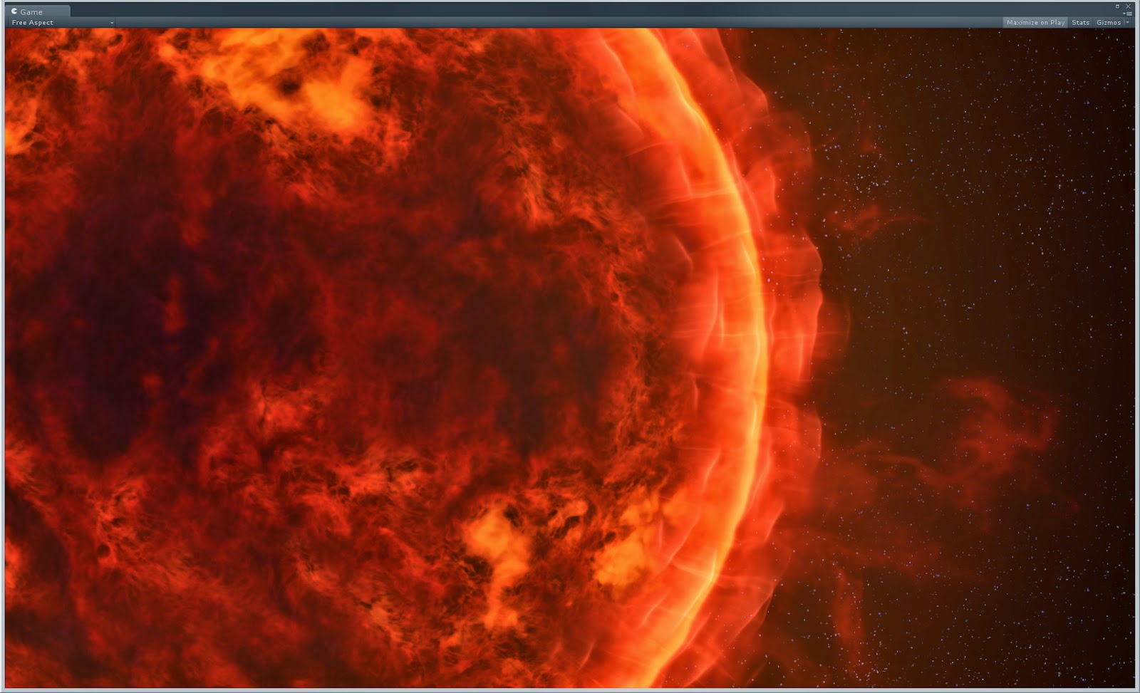
Final sun without and with heat haze shader

And so we have reached the end of the Sun Shader Epic.  I hope you enjoyed it and maybe learned something, but if not that's ok too.

Thursday, February 26, 2015

2.5D Sun In Depth Part 3: The Flares


The Flares:

The flares are the purple bottom most model in the above picture.

The model is a bunch of evenly spaced quads all aligned facing outward from the center of the sun.  The vertex color of each quad has been randomly set in 3ds Max before export to offset the animation cycle for each quad.


The textures were referenced from the ink section of CG Textures.  I built an alpha (as many of the inks are different colors) and the used a gradient map to make the color.

This  is a super simple pixel shader with a little bit of vertex shader magic to give it some motion.  People often underestimate the animation that can be done in a vertex shader.  I remember when Raven added vertex modulation to the Unreal material editor long before Epic added it standard.  I got into a lot of trouble making crazy vertex animations back then.  To see some real vertex shader magic check out Jonathan Lindquist's GDC presentation about the work he's done on Fortnite.  I would recommend the video if you have access to the GDC vault.

The Shader

Cull Off

This is one of 2 parameters that is different from the sun edge shader and it's purpose is to make sure that all faces of the material are drawn, front and back faces alike.  The reason for this parameter is so I can flip some of the quads left and right to get some variation and not have it go invisible because it's facing the wrong way.

Blend SrcAlpha One

This is one of my favorite blend modes because it takes any alpha blended shader you have and makes it additive.

struct Input {
float2 uv_MainTex;
float fade;
};

I've talked about the struct input in the sun surface post.  Here is where you see the actual usefulness of vertex interpolators.  In that first line I am passing into the pixel shader the uvs for the main texture.  In the second line I am passing in a custom float value.  This is a value that could be expensive to calculate on the pixel level but not need per pixel granularity.

void vert (inout appdata_full v, out Input o) {
UNITY_INITIALIZE_OUTPUT(Input,o);

float scaledTime = _Time.y * 0.03 * ( v.color.x * 0.2 + 0.9 );
float fracTime = frac( scaledTime + v.color.x );
float expand = lerp( 0.6, 1.0, fracTime );
float fade = smoothstep( 0.0, 0.2, fracTime ) * smoothstep( 1.0, 0.5, fracTime );
v.vertex.xyz *= expand;
o.fade = fade;
}

Ahh the vertex shader.  This is where most of the work is done.

inout appdata_full - This means that we are going to be getting all the information we can about the vertex (position, normal, tangent, uv, uv2, and color) and passing it in with a struct whose name is v.

out Input o - This means that the data we return needs to be in the format of our input struct and it's name is o.

UNITY_INITIALIZE_OUTPUT(Input,o); - This just sets up most of the busy work that the default vertex shader would normally do.  In this case the only thing is does is transform the MainTex uv coordinates.

float scaledTime = _Time.y * 0.03 * ( v.color.x * 0.2 + 0.9 ); - Now lets do some work!  This takes the global shader parameter _Time.y (which is the seconds that have passed since you started playing your level) and then scales it down and multiplies it by the red channel of the vertex color which has been mapped to be between  0.9 and 1.1.  Now each flare is doing it's thing at a slightly different rate!

float fracTime = frac( scaledTime + v.color.x ); - We take the scaled time and add the red channel of the vertex color to it and then take the frac of that.  This creates a repeating gradation from 0-1 that is different for each flare.

float expand = lerp( 0.6, 1.0, fracTime ); - Here we take the fracTime which is 0-1 and lerp it between 0.6 and 1.0.  That means that the scale of the flares will not drop between 0.6.

float fade = smoothstep( 0.0, 0.2, fracTime ) * smoothstep( 1.0, 0.5, fracTime ); - This is for fading the flares on and off over there animation cycle.  The start and 0, go up to 1, and end at 0 and then they repeat!

v.vertex.xyz *= expand; - This is where that vertexes actually move.  Multiplying a vertexe's xyz position is the same as scaling it.  So the model is  getting scaled between 0.6 and 1.0 over the animation cycle, except each flare is doing it at a different time.

o.fade = fade; - Just pass that fade value to the pixel shader so it knows to fade the flare on and off.  This is the last piece of the input struct as UNITY_INITIALIZE_OUTPUT already took care of uv_MainTex.

void surf (Input IN, inout SurfaceOutput o) {
half4 mainTex = tex2D (_MainTex, IN.uv_MainTex);

o.Albedo = 0.0;
o.Emission = mainTex * _Factor;
o.Alpha = mainTex.w * IN.fade;
}

This is as simple as a pixel shader can get.  Multiply the main texture by the _Factor parameter, and multiply the alpha by the fade parameter we passed in from the vertex shader.  And that's all there is to it!  The end result looks like the image below.  Notice how some flares are larger and further out than others.  This is due to adding the vertex color to the time.

Final Sun Flare Material


Sunday, February 22, 2015

2.5D Sun In Depth Part 2: The Edge Ring


The Edge Ring:

The edge ring is the orange model in the image above. The shader is much simpler than the sun surface so this will be a shorter entry.

The Shader

There is 1 main texture and 2 tiling parameters for it, 3 fire textures with tiling parameters, and a factor parameter to ramp the whole thing up and down.

Tags {
"Queue"="Transparent"
"IgnoreProjector"="True"
"RenderType"="Transparent"
}


There are more tags and extra bits of text at the beginning because it is a blended shader and needs to have a bit more information about how it is supposed the be drawn.

The Queue is when in the rendering pipeline this material should be drawn. A value of transparent makes it drawn after all off the opaque stuff has been drawn.

Setting IgnoreProjector to True keeps projector entities from trying to draw on this surface.

Setting RenderType to Transparent is useful for shader replacement which I'm not really worried about here. More info about subshader tags is available in the unity manual.

LOD 200
ZWrite Off
ZTest LEqual
Blend SrcAlpha OneMinusSrcAlpha


LOD has to do with limiting what shaders can be used from script. Idealy you would make a a few shaders with different LODs and fallback to them if performance was an issue.
ZWrite Off: don't write to the depth buffer.
ZTest LEqual: only draw if this surface is in front of opaque geometry (if it's Z value is less than or equal to the Z value of the depth buffer)
Blend SrcAlpha OneMinusSrcAlpha: This is for alpha blending, more blending modes are described in the unity manual

half4 mainTex = tex2D (_MainTex, IN.uv_MainTex * _MainTiling1.xy + _Time.y * _MainTiling1.zw );
half4 mainTex2 = tex2D (_MainTex, IN.uv_MainTex * _MainTiling2.xy + _Time.y * _MainTiling2.zw );

In these lines I just grab the main texture twice with different tiling parameters. The values for the first tiling parameter are (3,1,-0.01,0) this will tile the texture 3 times horizontally, once vertically, and scroll it ever so slowly horizontally. The values for the second parameter are (5,1,0.01,0) which tiles it a little more and scrolls it in the opposite direction.


half4 fireTex1 = tex2D (_FireTex1, IN.uv_MainTex * _Tiling1.xy + _Time.y * _Tiling1.zw ); 
half4 fireTex2 = tex2D (_FireTex2, IN.uv_MainTex * _Tiling2.xy + _Time.y * _Tiling2.zw ); 
half4 fireTex3 = tex2D (_FireTex3, IN.uv_MainTex * _Tiling3.xy + _Time.y * _Tiling3.zw );

In these lines I grab the 3 fire textures with their tiling and scrolling properties. these textures all tile multiple times horizontally and scroll up vertically with slight horizontal scrolling to help hide repeating patterns.  The first fire texture is the same as the wave texture from the sun surface, the second is similar but modifies slightly, and the third is like some stringy fire.


mainTex = ( mainTex2 + mainTex ) * 0.5;

I Add the 2 main textures together and multiply them by 0.5. This would be the same as if they were lerped together with 0.5 blending.

float4 edge = mainTex * mainTex;

I wanted a tighter edge so I multiplied the main texture by itself and saved it off to a variable. This can be made adjustable by using pow( mainTex, _SomeParameter ) and you will be able to adjust the tightness in the material, however the pow() function is more instructions than just multiplying things together multiple times.

mainTex *= fireTex1.xxxx + fireTex2.xxxx + fireTex3.xxxx * 0.3;

With the edge saved off I multiply the main texture by the sum of all my fire textures, the last fire texture was a little too much so I multiplied it down by 0.3;

mainTex += edge;

Add the edge back into the main texture.

mainTex.xyz *= _Factor;

Multiply the color by the factor parameter and we are done!

o.Albedo = 0.0;
o.Emission = mainTex;
o.Alpha = saturate( mainTex.w );

This is another unlit material so the main texture goes into the Emission and the blend mode needs an alpha so I saturate the main texture's alpha and put it there. The alpha needs to be saturated because when the edge was added to the main texture there is a possibility that the alpha could go over 1 and when the alpha is out of the 0-1 range the blending gets super wonky.

Below is the final result, keep in  mind that this will have the sun surface behind it.

The final result of the sun edge shader


Saturday, February 21, 2015

2.5D Sun In depth Part 1: The Sun

Some people are asking for more info on this asset.  Some people have asked for the asset outright.  While I can't give anyone the whole thing as then Dave wouldn't have an awesome unique sun for his game, I will explain it more in-depth and share the shaders so everyone can learn and make similar assets.  I'll start off with the sun surface and do an entry for each piece.


First off, Here is a better exploded view of the geometry.  From top to bottom is the haze, the ring, the sun, and the flares.  These are pushed much closer together before I export them from max.

The Sun:

The sun is the light blue piece of geometry in the picture above


There is a main texture (_MainTex) which is the color of the sun that I got off of a google image search.
2 fire textures (_FireTex1, _FireTex2) with tiling attributes (_Tiling1, _Tiling2).
A flow texture (_FlowTex) with a speed parameter (_FlowSpeed).
A wave texture (_WaveTex) and it's tiling parameter (_WaveTiling).
And finaly a factor or brightness parameter (_Factor) to control the intensity of the overall shader.

Something you may notice is that I only pass the uv's for the main texture into the pixel shader. The reason for this is because I tend not to use Unity's built in texture transforms. This eats up a lot of interpolators which I would rather have for other things. An interpolator is something that passes information from the vertex shader to the pixel shader. When you see the struct Input... each of those is an interpolator. Usually you can have something like 8 and I have run out on occasion.

float2 uvCoords = IN.uv_MainTex;

Lots of texture look ups are going to use the MainTex uv coords so I just store that off at the begining.

half4 mainTex = tex2D (_MainTex, uvCoords);

The main texture is the sun overlay. The sun overlay texture has the color of the sun in it's rgb channels and a mask to mask out where the fire will go. 
 

float4 flowTex = tex2D (_FlowTex, uvCoords);
flowTex.xy = flowTex.xy * 2.0 - 1.0;
flowTex.y *= -1.0;

The flow texture stores the vectors for direction the suns flames will travel in its x and y channels.  This was made in Crazybump using sun color map.  A normal map and a flow map are very similar since they are both vectors ;)  The z and w channels store a set of texture coords that will be used for the waves.  The z channel is just some low frequency noise and the w is the height from the normal generated by Crazybump.  This map is small and set to be uncompressed.  When dealing with flows and textures as texture coords it's better to have higher color fidelity than resolution.  I flip the y because it wasn't flowing the right way.  This could be done in photoshop before hand as well.


half4 waveTex = tex2D (_WaveTex, flowTex.zw * _WaveTiling.xy + _Time.y * _WaveTiling.zw );

Now we are going to grab that wave texture using the Coords that were stored in the flow map z and w component. The tiling parameters take care of the uv transforms in the pixel shader. Something I do A lot in my shaders is this:

uvCoords * _Tiling.xy + _Time.y * _Tiling.zw

The x and y of the tiling parameter work the same way as Unity's default tiling transforms and the z and w work the same as Unity's offset transforms with the added bonus that it is multiplied by the time which makes the texture scroll over time. This is also the only way to transform a texture who's uv coords derive from another texture.

half wave = waveTex.x * 0.5 + 0.5;

The wave texture is then brightened up as it will later be multiplied into the main texture. this is an optional step.

Other maps used for the sun

float scaledTime = _Time.y * _FlowSpeed + flowTex.z; float flowA = frac( scaledTime ); float flowBlendA = 1.0 - abs( flowA * 2.0 - 1.0 ); flowA -= 0.5; float flowB = frac( scaledTime + 0.5 ); float flowBlendB = 1.0 - abs( flowB * 2.0 - 1.0 ); flowB -= 0.5;

A big chunk! First we save of a variable for the scaled time since it is used twice. The flow texture's z component is added to the time to give it a little temporal distortion and keep the transition from A to B and back again from happening all at once. The flowA and flowB bits are very standard flow map bits of code. Check out Valve's extensive pdf on flow mapping in portal and left for dead for a better understanding of the technique.

half4 fireTex1 = tex2D (_FireTex1, uvCoords * _Tiling1.xy + _Time.y * _Tiling1.zw + ( flowTex.xy * flowA * 0.1 ) );
half4 fireTex2 = tex2D (_FireTex2, uvCoords * _Tiling2.xy + _Time.y * _Tiling2.zw + ( flowTex.xy * flowB * 0.1 ) );

half4 finalFire = lerp( fireTex1, fireTex2, flowBlendB );

Now we are finally looking up the fire textures.  I am using the tiling params to adjust to the repetition and the scrolling and adding the flow texture's x and y channels in multiplied by the flow amounts for each texture.  Then I lerp the 2 textures together based on flowBlendB which was calculated before hand. You actually don't even need flowBlendA.

finalFire = lerp( mainTex.x, finalFire, mainTex.w );

Now I lerp the main textures x channel into the final fire using the main textures alpha channel as a mask.  The fire will be multiplied into the final overlay texture and if you left it full strength it would be too much.  The mask is white in the mid values of the sun color and dark everywhere else, this means that the brights will stay bright and the darks will stay dark.

half4 Final = mainTex * finalFire * _Factor * wave;

All that's left is to multiply everything together!

o.Albedo = 0.0;
o.Alpha = 1.0;
o.Emission = Final.xyz;

This is really an unlit shader so I just set the Albedo to 0 and let the Emission to all the work. Below is the final result of this shader on the sun mesh.  It's not much to look at on its own but it's a good base for the stuff that will be piled on top of it.

The final result of the sun surface shader

Thursday, February 19, 2015

2.5D Sun


A friend of mine is working on a Rouge-like game, which was explained to me as a type of game where you die...  Or something.  Here's the link to his games blog so I don't butcher the explanation of it: http://theheavensgame.tumblr.com/ 

Anyway it's set in space so he needs some spacey effects and I thought it was a good opportunity to make a good looking sun.  Usually things like planets and stars have layers of volume materials which give them different looks depending on the viewing angle.  Think about how the edge of the earth looks due to the layers of ozone and atmosphere.  These are tricky and sometimes expensive to render because they have to work when viewed from every angle, but in this situation the sun only needs to be viewed from the front so I can set up a minimum number of layers depending on where I want to see certain visual elements.


The meat and potatoes is a squashed hemisphere to give the sun a little depth, There's an image of the sun I picked off of google with flow map that slowly distorts some fire textures.  There's also a look up texture that moves through the z component of the flow map. (flow in xy, height in z)  There is a ring around the edge to give it that ozoney Fresnel look.  There's also some wave textures and ray textures that scroll outwards from this ring.  The solar flares are 1 mesh with a bunch of outward pointing quads.  There is a vertex shader on them that pushes them on their tangent (outwards because the tops of the texture are out and the bottoms of the texture are in) and fades them in and out.  The flare vertex code looks like this:

fracTime = frac( _Time.y * yourSpeed ) ;
position.xyz += fracTime * v.tangent.xyz * yourDistance; //push the flares outwards
color.w = smoothstep( 0.0, 0.2, fracTime ) * smoothstep( 1.0, 0.5, fracTime ); // fade the flares in and out over the cycle

The whole thing is covered by a heat haze and glow which ties everything together nicely!

The final result looks like this: Sun Demo


Wednesday, February 18, 2015

Material Tool

I'm working on a image to material type of tool that fits somewhere between Crazybump and Bitmap2Material.  Giving you more control and options than Crazybump but probably not as robust as B2M.

So far I have...
Height from diffuse.
Normal from height with light direction from diffuse.
Ambient occlusion from height and normal.
Edge/height from normal.
Some options to high pass the diffuse and remove highlights and super dark shadows.
Spec and Roughness creation using the same features as the diffuse options.
A mostly physically based preview.
Seamless tiling of maps using height map bias.  I'll look into splat map tiling too.

The 2 aforementioned products probably already have most of the market share so this will probably be a free tool.  Its made in unity so the import options are limited but I did manage to get tga import working.  So far the it imports jpg, png, tga with the help of a nice library I found, and bmp.  I haven't looked too much into exporting but png and jpg work for sure and I will try to get tga and bmp working.

I also added a nice post process with some kind of inverse kawase depth of field blur which I might make a post about since it works pretty durn good and I haven't seen any articles illustrating the exact technique I used.